


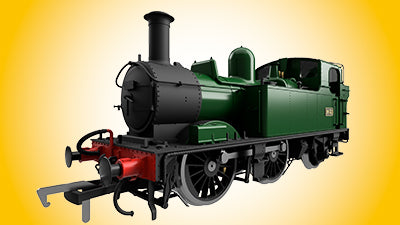
OO Gauge 4800 / 14xx & 5800 Class 0-4-2 Locomotive
All New OO Gauge Class 4800 / 14xx & 5800 4800 / 14xx & 5800 Prototype The 48XX and 58xx was designed to replace the earlier 19th. Century George Armstrong...
Please be aware the Dapol online catalogue is currently being updated and will be available again soon.
Welcome to the Dapol News section, here you can find all of the latest news and press releases that Dapol have posted on the website. The news articles are archived by month for the current year and then by year and month for older posts.
All New OO Gauge Class 4800 / 14xx & 5800 4800 / 14xx & 5800 Prototype The 48XX and 58xx was designed to replace the earlier 19th. Century George Armstrong...
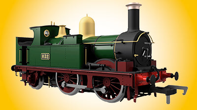
All New OO Gauge Class 517 517 Prototype The 517 Class were small 0-4-2T tank engines designed by George Armstrong for local passenger work on the Great Western Railway. 144 were built at Wolverhampton Works in 13...
![]()
Shipping Cost £3.95 for all orders
![]()
Shipping Cost £9.95 for all orders
![]()
Shipping Cost £39.95 for all orders
Copyright © Dapol
All Right Reserved.
Copyright © Dapol
All Right Reserved.


